Now with HTTPS!
PUBLISHED 7/9/2025
WRITTEN BY Christopher McRae
The idea of establishing an IP connection over a CB radio channel may sound completely absurd, and it kind of is. But TCP/IP and radio have a lot more in common than you think. Amateur radio operators have used packet radio to send IP packets for over 30 years. For this project, I relied heavily on Amateur radio software and practices to make it work.
A common approach to establishing TCP/IP links over radio is to use AX.25, derived from X.25 and designed for use in amateur radio. Historically, AX.25 setups consisted of a PC connected to the radio via a TNC (Terminal Node Controller), essentially a modem, which interfaced with the radio. Nowadays, most peopl opt to use a software modem such as Direwolf, which make use of your PC's sound card eliminating the need for a TNC. AX.25 also has native support under the Linux Kernel which makes it possible to easily add an AX.25 device as a native network interface.
My hardware consisted of:
I chose the D620 because it has an RS232 DB9 port and separate mic. and headphone jacks.
In order for this to work at all, each computer must be able to make the radios transmit at precise times. Most modern radios designed for amateur use support some kind of serial interface for PTT (push to talk), usually this uses the RST or DTR lines of a standard RS232 connection. Most amateur radio software allows for configuring PTT using this commonly agreed upon system. Neither of my radios, or any CB radio as far as I know supports a serial PTT setup as this kind of communication was never intended to occur on CB. Some radios also support VOX (Voice Operated Transmit), which is not supported by my radios and is far less reliable than a hardwired PTT connection but can be exploited if making a PTT interface is too difficult.
I also need a way to connect the radios to a PC's sound card. The TRC-435 has an external speaker jack in the back but no dedicated audio in port. The GE has none of these.
I started with the GE as I thought it would be the easiest. It's a small unit and is only held together by 3 screws.
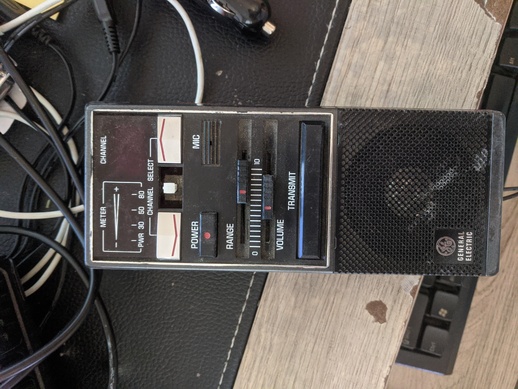
The GE 3-5910A
The first thing I noticed was a microphone that could easily removed and replaced with an audio input. Next was finding a good audio out point, I found a TOSHIBA TA7217AP IC that was the audio amplifier for the internal speaker, after looking up the schematic and trying a few locations for the audio output, I found a point to tap into that worked well enough.
Next was installing the PTT interface, which was more difficult. The transmit button operates a two position spring loaded switch that has 6 connections. The two common connections in the middle are shorted to either the top two connections or the bottom two connections depending on the button position. When the switch is not held and the radio is in receive mode, the middle terminals are shorted with the top two, and when in transmit mode they are shorted with the bottom two. With this figured out, I just needed to controls these shorts electronically.
I soldered 6 wires to each of the switch's legs on the other side of the mother board, then I connected these two a pair of relays which replicated the behavior of the switch.
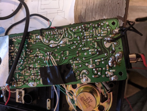
Back of motherboard with 6 PTT connections
Now I needed to drive the relays with the RST line of a serial connections and my PTT interface would be complete. Unfortunately, just connecting the RST line to the relays does not work as RS232 does not provide enough current to drive a relay coil let alone two. Even if there was enough current, RST does not go to 0v when low, it operates between -9 to -5 volts when low and 5 to 9 volts when high which would cause the relay to stay on at all times. To overcome this I needed a driver circuit, which after some research I found one could be implemented with a simple NPN transistor. I experimented with a few circuits until I made the one you see below.
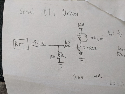
Schematic I used
The problem of driving a relay with a small digital signal has been well documented and solved by microcontroller users, especially in home automation where one might want to control a light or something with an Arduino or Raspberry Pi. In the case this project, using an optocoupler would probably be a better idea as it completely isolates the computer and the radio.
Modifying the Realistic was simpler because the radio did not need to be dissembled, I only needed to make an interface that connected to the mic. jack (a 5 pin DIN). I also discovered that the transmit button on the mic works in a very similar way to the GE (a 6 terminal switch that shorts two pairs of connections at a time). Because of that similarity, I was able to reuse all of the circuity I designed for the other radio, the only difference was figuring out which wires corresponded to which pins on the mic connector.
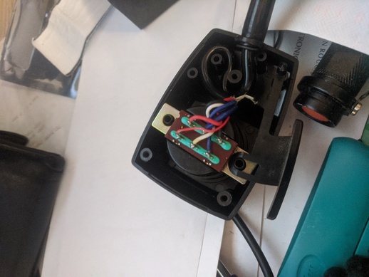
6 terminal switch in mic
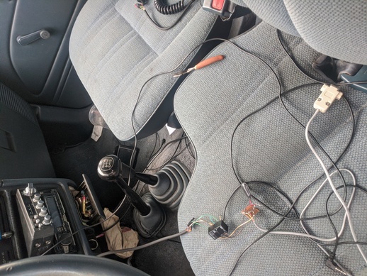
Custom mic interface
Finally, I could start testing it.
I started off with sending some SSTV (Slow Scan Television) images to ensure that I could transmit and be heard on both radios. It worked, here are some samples:

GE to RS (started receive late)

RS to GE (skew not ideal)
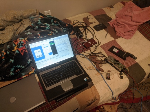
The GE setup (older verison of the interface is pictured, final does not require 9v battery)
This allowed me to configure my audio levels (very important for digital modes).
I then setup an AX.25 connection and used axcall to establish a connection between the radios, this unfortunately didn't work very well at 1200 baud so I lowered it to 300 baud, generally used on HF (High Frequency), and it worked. It turns out that my sound quality from the transmit side of the Realistic radio was not very good, I'm not sure if that is a problem with the radio or my interface, so I switched to 300 baud for all further communications. The picture below shows a few packets that were received properly at 1200 baud (KC2PQ-1 is the Realistic station)
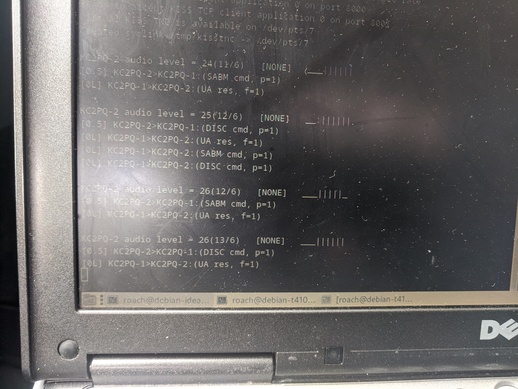
Direwolf showing packets between the two stations
Then I setup an TCP/IP connection on both systems and tried sending IP packets. Initially, not much was working but then I was able to successfully send a packet using ping.
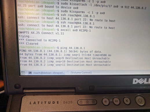
6586ms ping over 300 baud via CB radio
My end goal was at least getting telnet to work but that was unsuccessful.
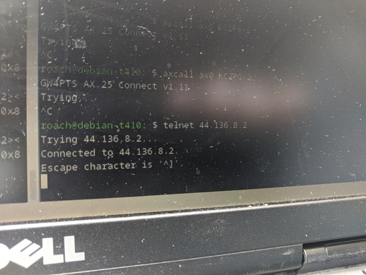
The extent of my telnet success
I also tried SSH but that appeared to timeout as well.
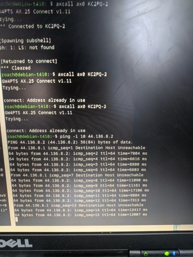
Pinging every 20s proved to be somewhat reliable
After experimenting for over an hour, I was only able to reliably send ping as I believe the 300 baud link was to slow to even establish a simple telnet connection.
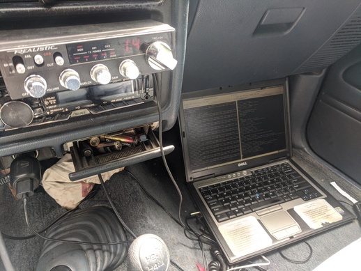
Setup in my truck
After working on this project for 4 days, I am satisfied with the current results. Even though telnet and SSH didn't work, getting consistent pings via a CB radio link is in itself good enough. If I am able to get 1200 baud working properly, I will try telnet and maybe even HTTP. Hopefully I can at least get those ping times down to something more reasonable.
Of course none of this is practical and was only done because I can. In the realm of decentralized communications, something like this may prove useful.
I also made sure that the radios were operating at a very low power in order to prevent from interfering with other CB users.
Each laptop is running Debian Linux (version 12 on the Realistic station and version 11 on the GE station). All programs were easily obtained through the Debian repository without the need of compiling anything from source.
Here are some of my config files:
/ete/ax25/axports
ax0 KC2PQ-1 1200 255 1 CB (1200 bps)
~/direwolf.conf
ADEVICE plughw:0,0
PTT /dev/ttyS0 RTS
MODEM 300
FIX_BITS 1 AX25
/ete/ax25/axports
ax0 KC2PQ-2 1200 256 1 CB (1200 bps)
~/direwolf.conf
ADEVICE plughw:1,0
PTT /dev/ttyS0 RTS
MODEM 300
FIX_BITS 1 AX25
NOTE: I realized that my axports files differ in terms of packet length, this may have contributed to problems with telnet and SSH.
Direwolf start command:
direwolf -c direwolf.conf -t 0 -p
Command to attach virtual TNC and configure ip address:
sudo kissattach -m 256 -l /dev/pts/* ax0 44.136.8.1
sudo kissparms -c 1 -p ax0